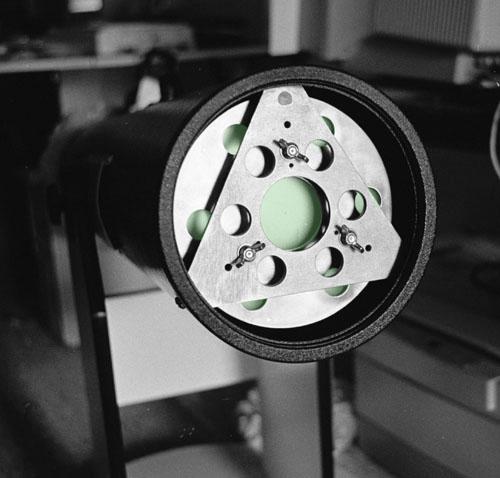
Discovery mirror cell after modification:
The large center hole shows the mirror's rear glass surface as do the smaller circumferential holes on the inner plate (depicted in false color for clarity). The holes should allow for better airflow and quicker cooling of the mirror.
The photos and plans below show more details...
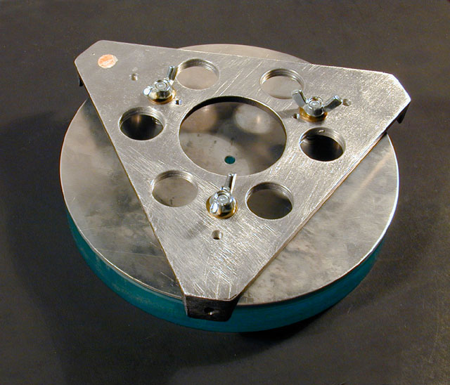 |
Photo of modifications to only the
mounting bracket. The round aluminum plate adhered to the mirror is still
untouched in this view (click to enlarge). I used a hole saw to cut the holes in the thicker mounting
bracket. The thinner aluminum mirror mount plate had to be detached before
holes could be punched. Detaching the mirror was done with a serrated bread knife using Palmolive detergent as a lubricant to cut through the existing silicon beads. It cleaned up easily with water. Brass washers under the collimation wing nuts make adjustments smoother . |
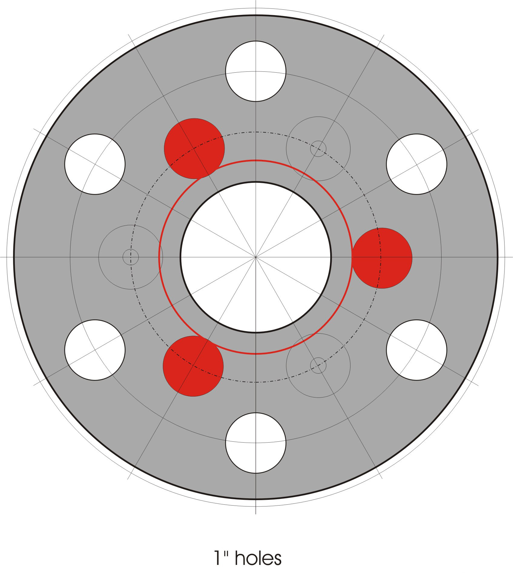 |
Plans for modification of the mirror
mount. The area shown in red is the pattern for adhesive silicon to
attach the 8" mirror. The attachment pattern (in red) was calculated using
GUI-PLOP. Holes were punched using chassis punches that I already owned. The mirror must be detached to punch the holes. The downloaded file of this pattern (at 200 dpi) should print to scale, but may be automatically downsized in your browser. Right-click and choose "Save Target As..." to download the full resolution version for printing. |
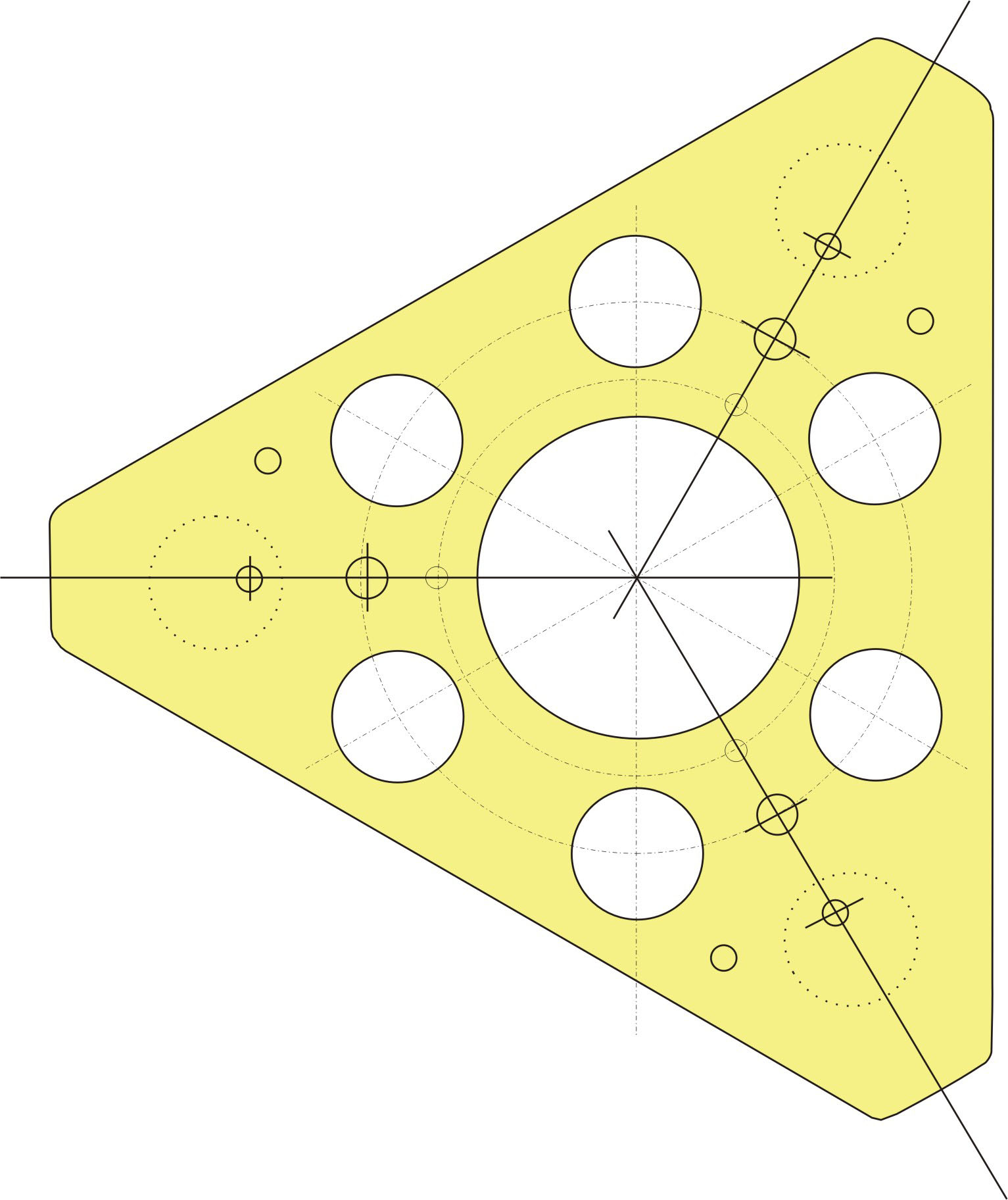 |
Plans for modification of the mounting
bracket.
Other miscellaneous small holes shown here were for experiments using a University Optics
mirror mount, but I returned to the adhesive-mounted mirror configuration in
the end. The downloaded file of this pattern (at 200 dpi) should print to scale, but may be automatically downsized in your browser. Right-click and choose "Save Target As..." to download the full resolution version for printing. |
Bill Schneider
updated February 5, 2007