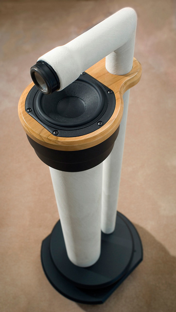

Late August, 2007: I'm finished! They sound wonderful!
Here's what my Pluto Loudspeakers look like. I made some significant deviations from the published plans -- mostly for aesthetic reasons.
As promised on the Linkwitz website, they image acoustic space much better than other speakers I have owned. They are also the most distinctive looking speakers I have owned, although one could argue about their aesthetics.
Build Log
The following steps outline the design, fabrication, and assembly of this set of Plutos. Keep in mind this is a departure from the published design available from Linkwitz Labs.
Click any picture to enlarge...
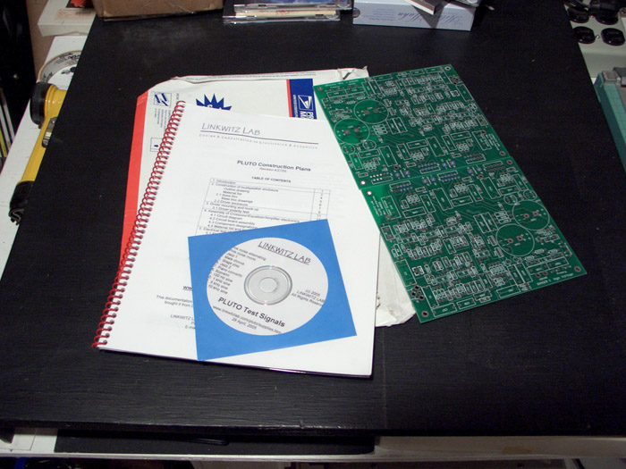 |
March 2007: I've ordered the plans and circuit
boards from Linkwitz Labs. <--click any picture to enlarge |
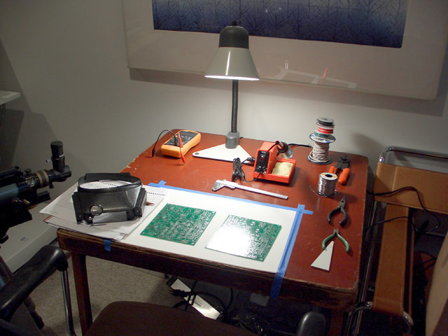 |
I've ordered a Weller soldering station and
Tenma digital multi meter
(DMM) from MCM
electronics online. I'm pleased with both of these tools.
This is my temporary soldering station - a card table to which I taped a piece of heavy cardboard to protect the surface from burns, etc.. |
|
|
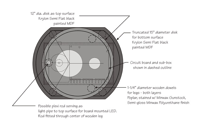
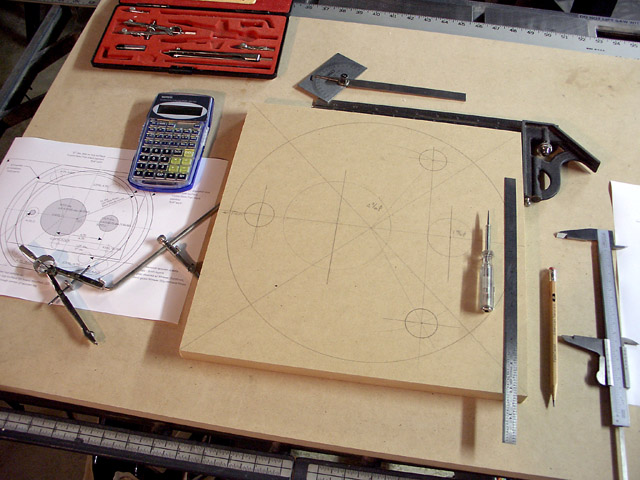
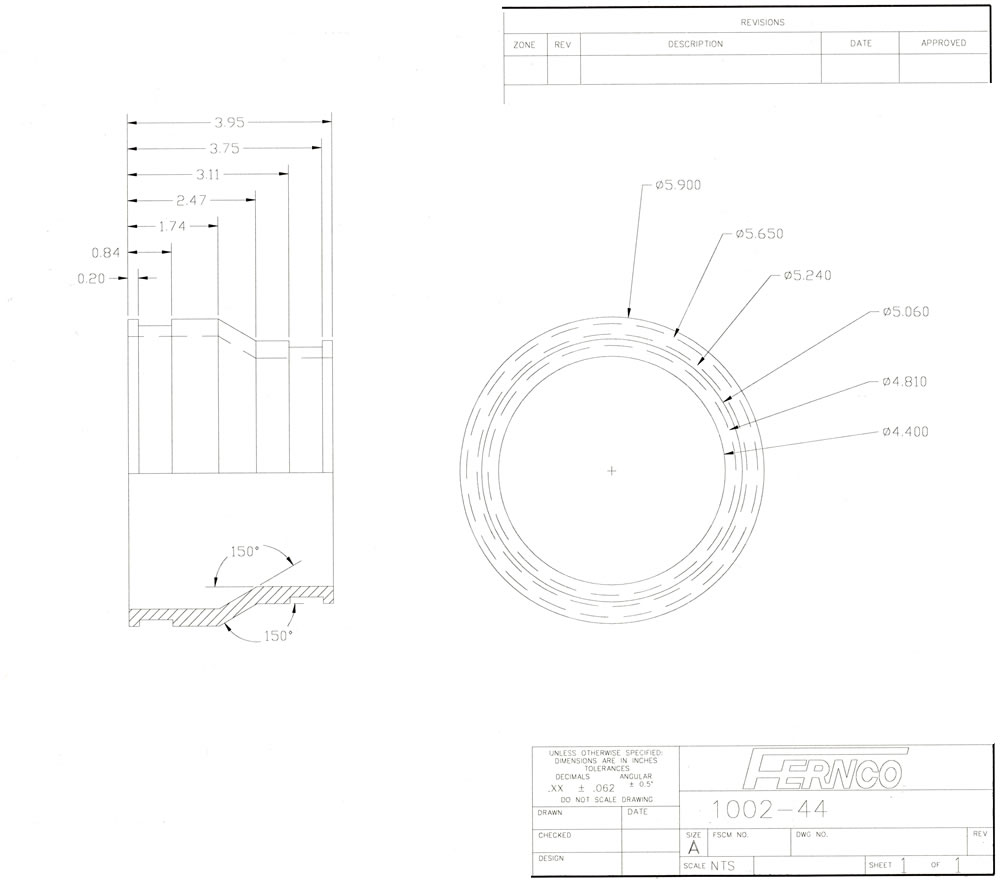
Here's a preliminary sketch
of how I'd like the Plutos to look. The
standard plans suggest gluing the woofer to a
Fernco rubber boot,
but I'd prefer something different. I plan to make the coupler out of
a stack of MDF rings that are laminated together. Also, I'd like to do something
different with the
base to play upon the circular shapes in the design. While this is how I'd like them to look, there are several obstacles to fabrication. Among the most challenging are the wooden dowels on either side of the woofer pipe. I'd have to mate them to the curve of the woofer pipe by either milling the back side of the dowel concave to match the pipe (or some variation of that), or I'd have to mill a flat in the 4" woofer pipe to accept a flat on the rear of the dowel. (NOTE: In a previous iteration of design, the long dowels served a purpose, now they're just decorative. In the end, I decided to not use the woofer pipe dowels.) The electronics would be housed in the lower chamber, and large air holes and slots in the first horizontal plate would provide good ventilation. The second horizontal plate would hide the holes from view and from poking fingers. The bottom surface will likely be a truncated 15" diameter circle. The upper layer in the "layer cake" would be circular, going with the round theme offered by the pipes.
|
 |
Here's one whimsical approach that could possibly have a high WAF.
Just kidding! |
|
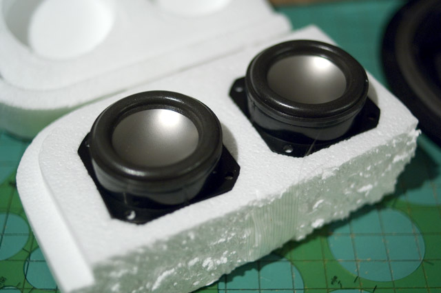
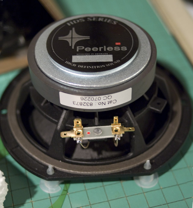
June 12, 2007: The drivers have arrived from Madisound. Aura NSW2-326-8A tweeters
and Peerless 832873 (= 830873) mid/woofers are used for the Pluto. These
were ordered together with some Acoustistuff material to damp sound
inside the pipes. Total cost of this order was around $160. |
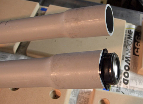 |
July 17, 2007: I've thought about using PVC conduit
instead of the regular PVC pipe and couplers specified in the plans. Conduit has
an integral flare that may make the tweeter mount more elegant. I also
want to miter the right-angle joint between the vertical and horizontal sections. This
means that I must produce an accurate, clean cut. The conduit comes in 10 foot lengths, so there's plenty of spare pipe to experiment with. Each conduit is a reasonable $6 at a local mom-and-pop hardware store. |
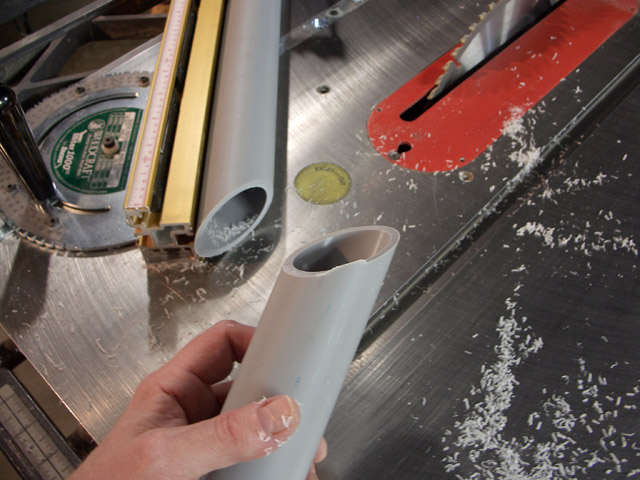 |
My first experiment was to see if my table saw could make a clean miter cut through the PVC pipe. Success! It cuts like a dream on the table saw and has a very smooth surface. This will make a good fit for gluing the miter joint. |
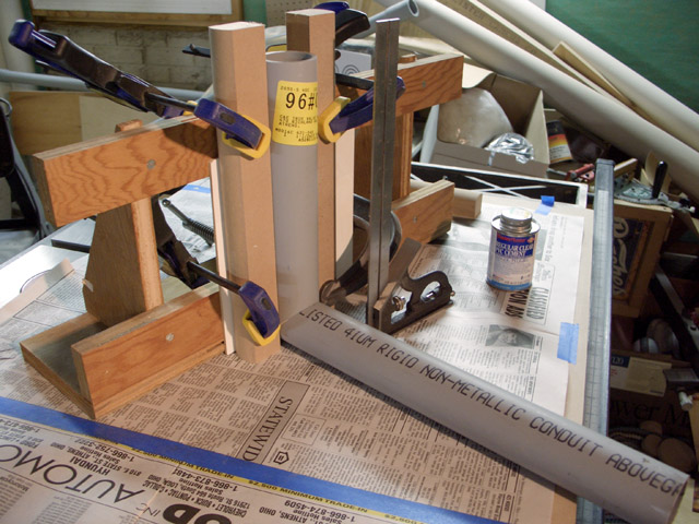 |
Without using the conduit end - just the unused cutoffs - I experiment with methods for holding the conduit square while glue dries in the miter joint. |
 |
After a day dry time, the glued test joint is strong, and I give this process a green-flag for use in the final project. |
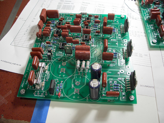 |
June 24 2007: I've been soldering the circuit boards. They are almost done, but I'm awaiting backordered parts from DigiKey. |
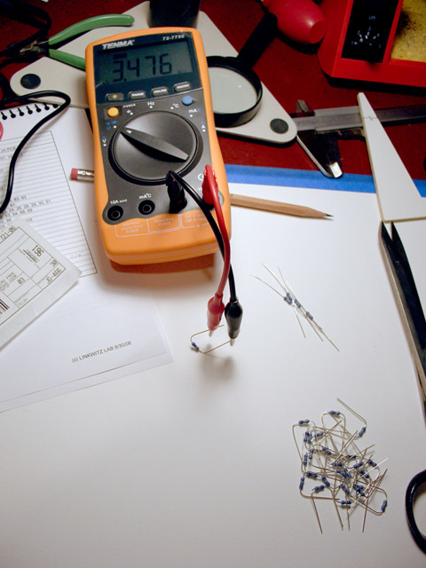 |
One thing I do to minimize
trouble down the road is to measure each resistor and capacitor before
they are soldered into the circuit board. An out-of-spec resistor or
capacitor would be hard to find after the circuit board has been
assembled. The DMM is a $45-ish unit purchased online from MCM electronics. It doesn't measure inductors, but there are none in this project anyway. |
 |
June 30, 2007: I want to
substitute Plexiglas for the circuit board mount
instead of a piece of plywood. Plexiglas has visual appeal, and the cost
is reasonable for such small parts. The local glass shop cuts a couple pieces of acrylic for me for $6 each. I planned the holes and geometry using CorelDraw software, printed the plan to a laser printer, and used the printout as a template to mark holes and cutouts. This file, saved in TIF format, is available for download here (1.8MB TIF file), Note that the circuit board shape may have changed since I built mine. If you are following these notes for your own construction, double check your own boards first. |
 |
Here are the plans as I
drew them for my needs. I didn't record the hole diameters for the
mounting screws and a few other items, so you're on your own there.
|
 |
July 1, 2007: This shows a test fit of the circuit board and
transformer on the Plexiglas board. It is made to exactly the same
dimensions of the standard plywood mount - with the exception of making
a cutout area directly under the heat sinks for improved airflow. See the next frame
for details. So far, so good. |
|
|
Because cooling of the output semiconductors has been a continuing topic in the Orion Users Group, I decide to relieve the support acrylic to permit direct airflow past the cooling heat sink. This photo shows how I cut the acrylic to do this. |
 |
I continue to ponder how the mechanical construction will be done while I solder circuit boards. This is a preliminary CorelDraw 'sketch' for how the upper-end might be done. I plan to fabricate the woofer mount out of glued rings of MDF. My goal is to reproduce the internal geometry of the Fernco fitting in MDF, but perhaps allowing a bit more 'breathing room' for the woofer magnet where the diameter necks down. It's tight in the standard rubber fitting arrangement, and maintaining good airflow around the speaker magnet is one concerned voiced often by SL. |
 |
Here are some concepts of how I might mount the tweeter to the flared conduit. I decide to use the simplest, the top version. I will however eventually put a small set screw (#8-32) into the bottom of the flare to press upward (gently) against the tweeter body. |
 |
July 1, 2007: Design-wise, I want to play on the round shapes present in the Pluto. I work on a round base large enough to hold the circuit board underneath, but find that the diameter gets excessively large. I decide to truncate the lower circular shape, and to add a smaller round piece above the main shape to hide the cooling vent and prevent careless fingers from touching the amplifier parts. |
 |
This shows the dimensions used to create the top parts of the base. I've employed some Cartesian x,y coordinates ( i.e., -1.433,0) to locate some of the features. It was just easier to do this in the CorelDraw software that I employed to create the plan. |
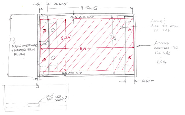 |
July 3, 2007: I sketch up plans for the box to enclose the circuit board. It will be affixed to the bottom of the Plutos. The attachment method will be long screws in countersunk holes in the 1/2" pine ends. These screws will tap into the bottom surface of the truncated round base. |
|
|
Here's the elevation plan
to allow for clearance for the tall power capacitors. Not drawn to
scale, of course. Be sure to account for any mounting bolts in the assembly. I didn't, and the caps came VERY close to contacting the bolt head that held the woofer pipe in place. Close call! |
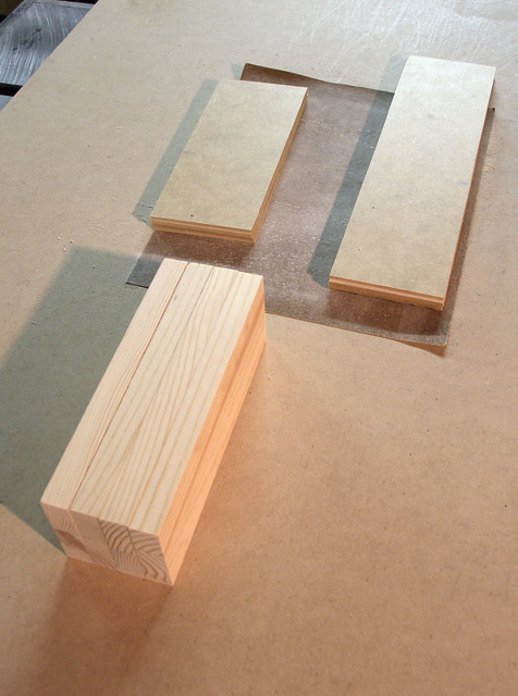 |
July 3, 2007: I cut the boards for the circuit board box according to the plan above . They are made from pieces of pine and thin MDF that I already have on hand. |
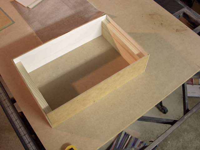 |
July 3, 2007: Here's the circuit box parts dry fitted. |
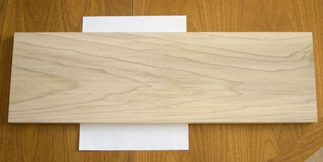 |
July 7, 2007: I went to Lowes to find a suitable piece of wood for the woofer mount. This piece of Poplar has a nice appearance grain-wise. Poplar is cheap, and not usually considered a noble wood to be used where appearance is important. I am determined to find a way through clever staining and finishing! |
 |
I experiment a bit with the
LED for the circuit board. I chose a Plexiglas
circuit board because it might conduct light from an LED soldered to the
circuit board to the front of the unit. In this experiment, a white LED
is placed into a hole drilled on the Plexiglas circuit board to see if I
could see the light from the front. I had drilled another hole for the
transformer in front of the LED hole, and it cast an unsightly 'shadow'. This
approach would also require a slot on the front panel, and that's
troublesome to machine. In the end, I didn't use the Plexiglas as a
light pipe to conduct light. It was an interesting experiment though. I may employ the light-pipe concept in another project someday. |
 |
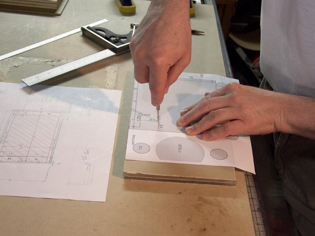
July 9, 2007: I begin laying out the cut pattern for the base parts onto pieces of 3/4" MDF. This is the smaller top panel. Circular shapes are to be cut using a router and a Jasper circle guide. |
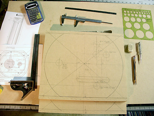 |
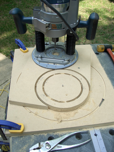
This is the layout of the bottom panel. It's more complex than the top panel. The flat, truncated part will be cut on a table saw before the circular part is cut. Circular cuts are made using a Bosch plunge router and a Jasper circle guide. |
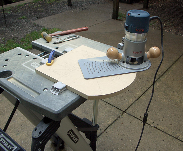 |
This shows how the router cuts the
radiused ends of the bottom panel. The panel was clamped to the work
table, the pin for the Jasper circle guide inserted into the center of
the panel, and the router was swung around the pin. I used a 1/4" spiral
upcut bit for cutting the radius, taking about 3/16" additional depth
for each pass until cut through. Tip learned in a later project: Rough cut the round part using a jig saw or a band saw leaving about 1/8" extra material. Then trim the remaining material using a router and a larger 1/2" router bit in one pass. It will produce a smoother surface and reduce sanding compared with multiple small cuts necessary with the 1/4" upcut bit. It's faster too. |
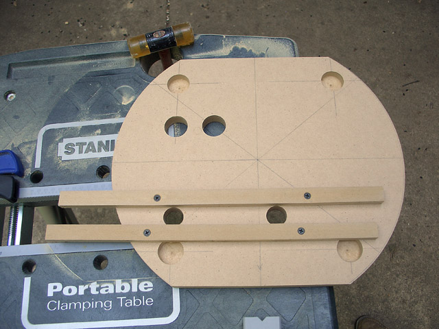 |
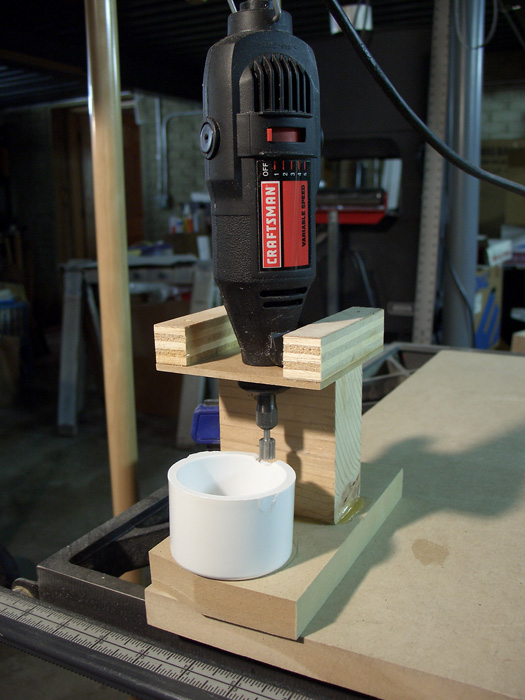
To make the cooling slot, I drilled two holes and then screwed some scrap pieces of wood in position to guide a pattern bit with the router to cut the straight sides. Pattern bits have a ball-bearing on the end to ride against a guide surface. |
 |
I used a hand-me-down Sears router table to chamfer the air vents to provide a kind of "venturi". I don't know if it will enhance cooling air flow much, but it sure won't hurt. |
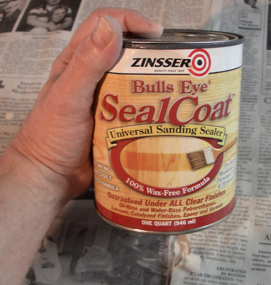 |
Time to think about
finishing. MDF soaks up spray primer like crazy. To seal the MDF so that
wont require so much spray primer, I used Zinsser Bulls Eye Seal Coat.
It seals MDF very well, and makes painting later SO much
easier. It penetrates into the MDF, dries quickly, and hardens the exterior so it is
very sandable. It saves a huge amount of finishing time. This was another tip learned the hard way after building a previous pair of speakers. I LOVE Zinsser Bulls Eye Seal Coat now. |
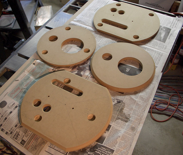 |
Here are the drying parts after sealing. The sealer hardens the surface nicely. |
 |
Wood - be very afraid! |
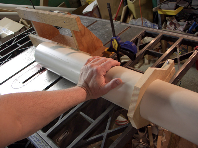 |
This didn't work! I attempted to cut the 4" pipe using my table saw and a homemade widget to position the pipe. The goal was to rotate the pipe to get a square cut, but I quickly abandoned this approach. It quickly became apparent that there's some kickback danger with this idea. |
 |
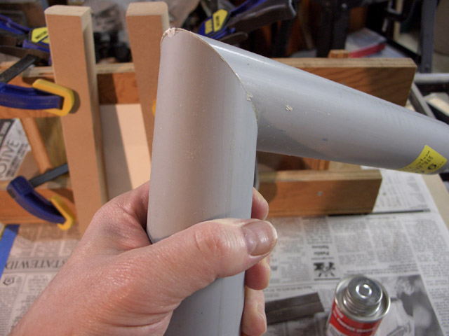
This DID work. A bandsaw that my father gave to me a week ago was able to cut the 4" pipe fairly evenly. A plumber later suggested a miter saw for 4" pipe to get a very square cut. I'm satisfied with the cut made on the bandsaw. |
|
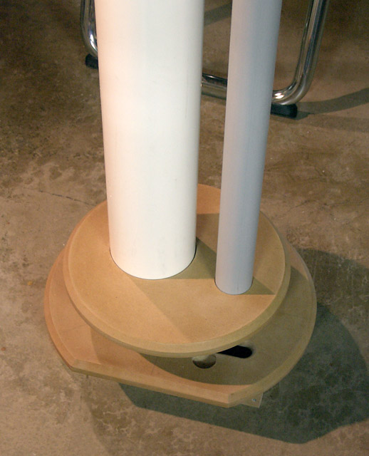
Am I on the right track?
Time to check. I dry-fitted the unfinished parts to check fit, and to preview how things might appear after assembly. Not bad! |
| Fabrication of the Wooden Dress Plate (woofer mount) | |
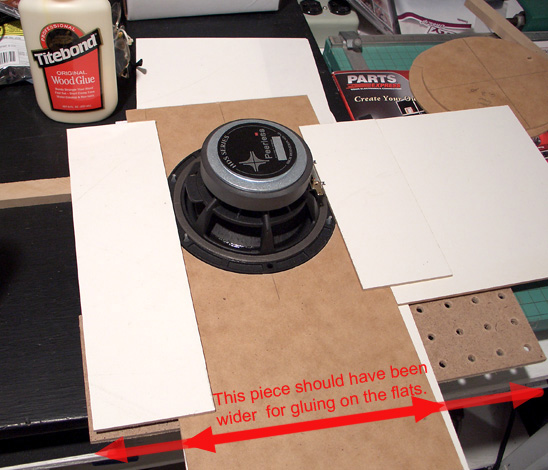 |
I wondered how to make a
non-round recess for mounting the woofer. I found this method in a DIY
forum after I posted the question. Thank goodness for the internet! I used thin 1/8" pieces of MDF for creating the initial template for the irregularly shaped woofer. Because its shape is a truncated circle, I routed a full circle in the thin MDF, then positioned additional straight pieces next to the flats of the woofer. I allowed about 1/32" clearance from the edge of the speaker to the flats to accommodate any small errors. I tacked these parts together using wood glue, and let it dry overnight. Then I lifted the woofer out leaving the opening with the desired shape and size. This formed a temporary template that I could use to route a stronger template in 3/4" MDF in a following step. In retrospect, the first through-circle for the woofer should have been routed in a somewhat larger area piece of material. The flats didn't have much overlap for gluing.. By the time I was done, this thing had all sorts of "wings" glued up to make sure it didn't fall apart when routing the final pattern in thicker material. I used this thin template to route the
pattern deeper into a stout 3/4" piece of MDF. To route the final
pattern, I used a pattern bit with the
follower bearing at the top. I purchased a short 1/2" diameter by 1/2
inch long pattern bit with the bearing at the top from
MCLS online. I
bought their Katana bit #16509 to do this work (see picture of it being used
below for the final routing of the dress plate). |
 |
The 3/4" MDF template was
then fastened to the dress plate with screws in non-critical areas. Routing the
truncated-circle woofer flange recess was very easy using this method. A
circular through hole in the center for the woofer is cut in a subsequent
step using a Jasper Circle Guide. I used a short 1/2" diameter by 1/2 inch long pattern bit (with the bearing mounted at the top) purchased from online store MLCS. I bought their Katana brand to do this work. MLCS have good prices and fast delivery. |
 |
Here are the plans for cutting the dress plate. I made two dress plates from one piece of Poplar purchased from Lowe's. I cut the exterior shapes and through-holes right after routing the woofer recess in it. All cuts were penciled onto the wood, and all holes for the Jasper circle cutter pins were drilled in the correct locations. A center punch was used to dimple the hole centers in their precise location before drilling. |
 |
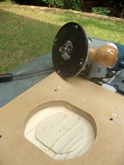
This picture shows routing the dress plate
using a Jasper Circle guide. The woofer recess has already been cut, but
not the woofer through-hole. I used a 1/4" spiral upcut bit to make the
cuts. I took 3/16" deep cuts with each subsequent pass until I
cut through the material. I had to be careful that I didn't cut the woofer through-hole away before the outside was done. The center for the outside shape is included in the hole. If the hole had been cut first, I would haven't been able to cut the outside shape concentric. |
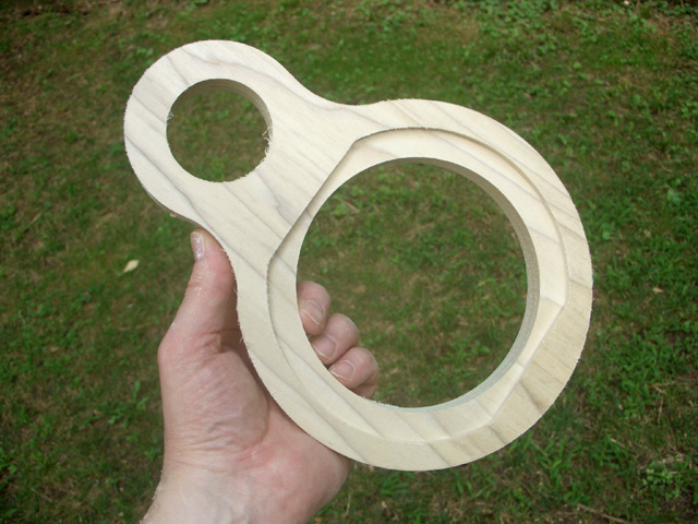 |
Here's the piece of poplar with all cutting done. All that remains is to put it onto the router table with a 45 degree cutter to chamfer the outside edge. And drill speaker mounting screw holes, of course. I used #8-32 Hurricane nuts on the underside of this part to hold the machine screws used to mount the woofer. |
| MDF Assembly to Replace the Fernco Fitting | |
 |
(Note: Fairly large
picture. It might be best to download it first, then print it out.) Here are the (sorry!) partly hand-drawn plans for the MDF rings that get stacked to make the woofer mount. It is a substitute for the Fernco fitting in the Pluto. These were made from both 3/4" thick and 1-1/8" thick MDF. The 1-1/8" thick MDF was a stair step from Lowes. When drilling the center pin for the Jasper circle cutter, I also drilled some 1/8" holes for assembly pins to be inserted later. Two MDF blanks were temporarily pinned together at the center (where the Jasper pin was to go) and two other holes were drilled in the "meat" of the rings so that they would align properly during final assembly. Think through the drilling of pin alignment holes so that you don't end up with an external hole where you don't want one. This illustration also shows how I had to increase the center to center distance between woofer and tweeter pipe to accommodate the extra diameter of the MDF woofer mount. It's thicker than the rubber fitting. |
 |
This shows one of the MDF rings that were eventually laminated together to form a woofer mount instead of the rubber boot of a stock Pluto. In the picture, it's being routed. I left several little thin 'spokes' to keep the center attached to the ring. I didn't want the router bit to chew into a piece that had just been cut loose. |
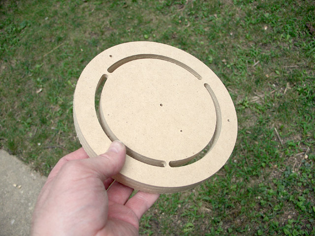 |
Here's one that is
almost done. A small hand saw separates the inner
circle from the ring, and a small sandpaper drum in my drill press cleans up the burrs. Note the alignment pin holes in the "meat" of the MDF ring. These were drilled at the same time the Jasper Guide center pins were drilled, and align exactly with the holes of an adjacent ring because the rings were drilled together. |
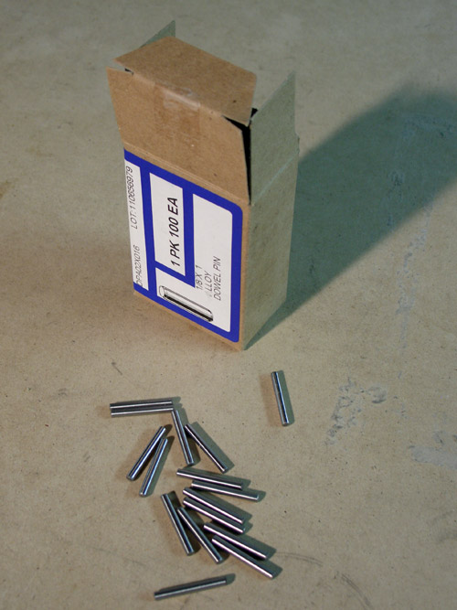 |
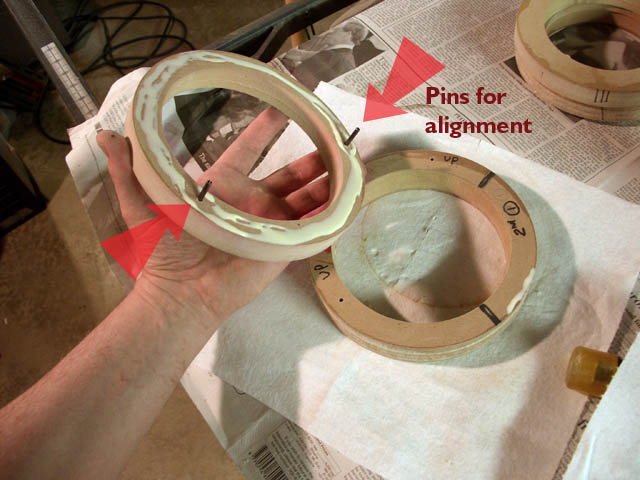
To locate the 4 rings
precisely for gluing, I used pins. Before the rings had been routed,
I had drilled both the center holes and the locating pins on each
adjacent blank. I drilled the center holes first, pinned the two pieces
together and drilled another hole in the proper location (part that
wouldn't be cut away during fabrication), pinned that hole too, then
drilled the last hole. The adjacent rings are then pin-registered to
each other for final assembly. The box of steel dowel pins was purchased online from McMaster-Carr |
 |
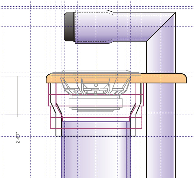
This assembly drawing hints
at the placement of the pins that registered the MDF rings together. The
rings were glued together in a later step to provide a substitute for
the Fernco rubber coupling.
The necked-down portion of the Fernco fitting is shown in a dashed green line. My design provided a little more "breathing room" for the woofer magnet. The dashed red line shows the inside profile if a 45 degree chamfer bit had been used on the inside of the MDF ring. I used a steeper 30 degree bit to make a sharper angle down to the 4" pipe to further help woofer breathing. |
 |
I dry fitted the parts together to get a sense of how things were coming. The dress plate hadn't been chamfered at this point, but you can see the woofer flange recess and a small 1/16" deep recess on the underside of one of them. The underside recess allowed my to locate the MDF ring assembly accurately to the dress plate. |
 |
Gluing the MDF rings together. The alignment pins located the parts so that they wouldn't slip side-to side. |
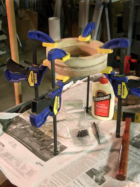 |
I used alternating layers of 3/4" MDF and 1-1/8" thick MDF for the woofer mount. The thicker 1-1/8" MDF was a piece of a stair step that I bought from Lowe's. |
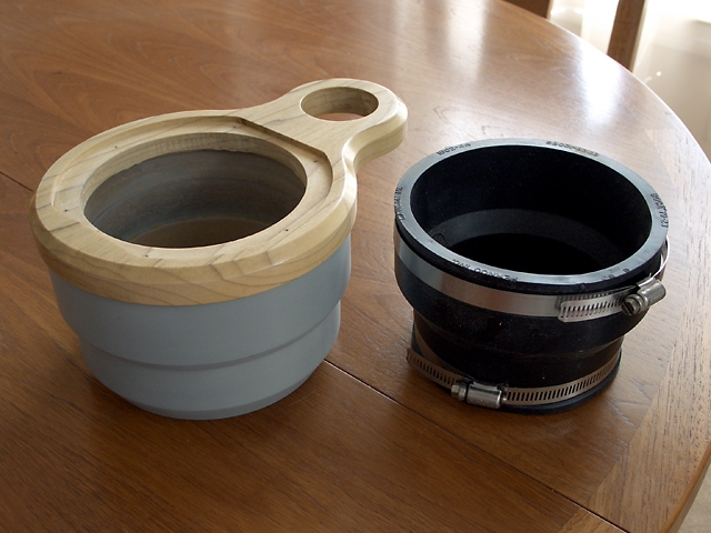 |
This picture shows a comparison between the Fernco fitting and my homemade parts. I attempted to match the interior shape of the Fernco fitting but I did leave a little more room where the fitting necked down to meet the pipe. My necked-down area was somewhat lower than the original to allow more airflow around the woofer magnet. |
| Fabricating Legs for the Base | |
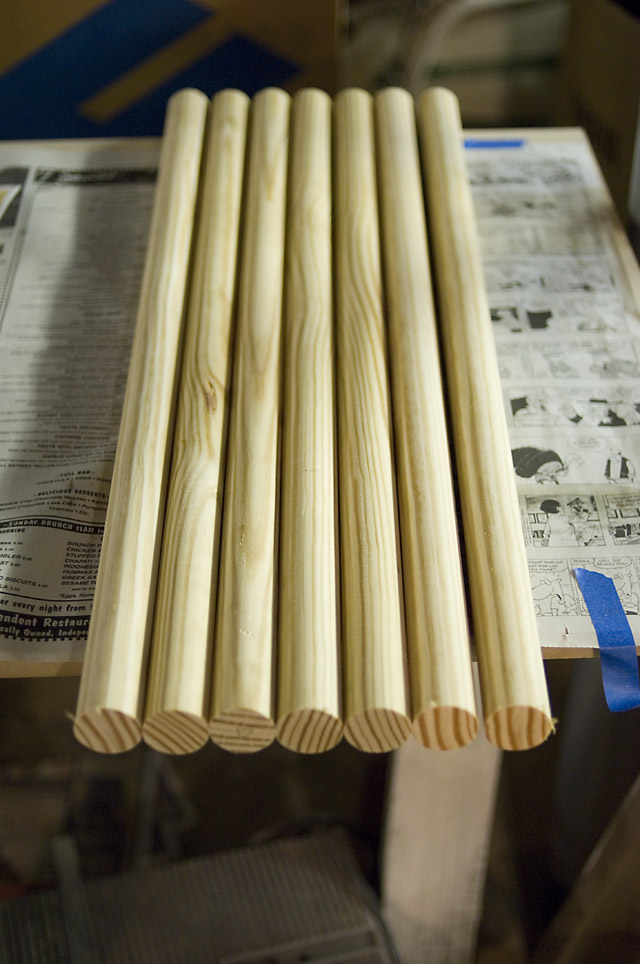 |
I bought 3 foot lengths of 1-1/4" dowels
from Lowes for this project. I discovered that 10' lengths of so-called 1-1/4"
handrail dowel is slightly oversize, and needs sanding. That's why I
used the 3' sections instead. The wood is ordinary poplar. |
 |
I cut the lengths into
sections slightly double the length that I'd need. After finishing, I'll
cut them in half and trim to the correct length on my table saw. I used a 1/2" round-over bit in my router table to round each end. |
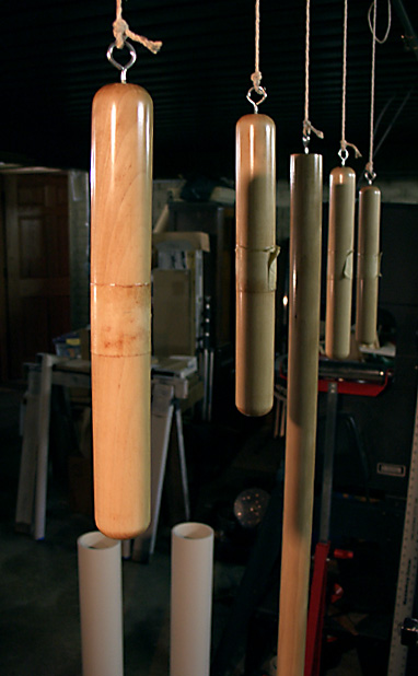 |
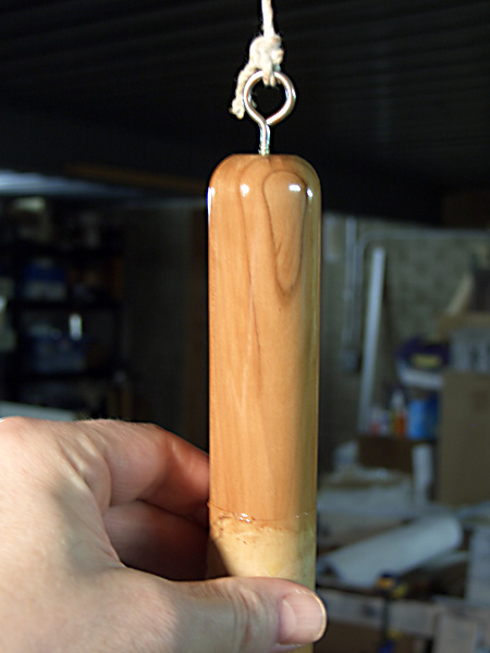
The pieces are hung by strings for finishing and drying. The center of each section has some masking tape wrapped around it to keep finish from building up there. This makes for a better fit into the base. |
| Finishing and Painting | |
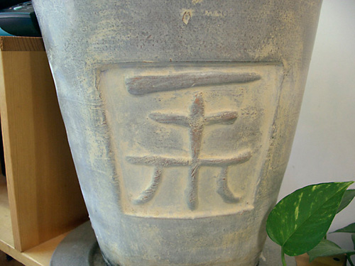 |
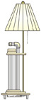
This vase was my inspiration for a rough, almost pottery-like finish for the Pluto pipes. I didn't want a glossy finish. I found the faux finishing section at Lowe's to be inspirational. I settled for a Texture Lime wash over antique stone latex paint. |
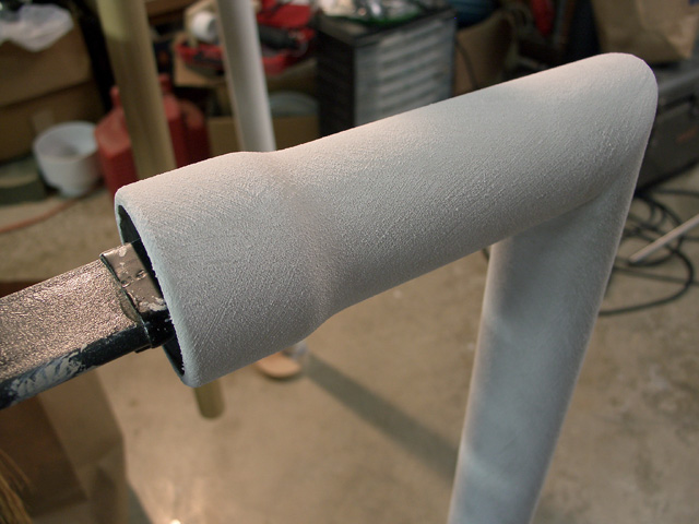 |
The finish for both pipes was a faux finish from Lowes over a Zinsser stain seal primer (alcohol based). The first coat was a flat 'ancient stone' latex, over which I put Textured Lime Wash using a brush with angled strokes. Over that I painted a clear faux-finish glaze to protect the delicate lime wash. |
 |
This picture shows the woofer pipes painted with the same Textured Lime Wash from Lowes. |
 |
This is the clear polyurethane with
which I finished the legs and the dress plate. This brush was used
first, and I found it to be better than hardware store paint brushes. In
the end, I used a cloth to wipe the poly onto the parts, and I believe
that the wipe-on method was better. I also used Minwax Gunstock color
stain with the Minwax polyurethane. To apply, I used two coats of polyurethane over the bare wood, then stained, then applied more poly as a top coat. This is an unusual method to prevent blotches and dark grain that I got when using the stain normally. The stain behaves oddly over the polyurethane, looks like it won't level out, but does. I also found that I couldn't "brush-up" an area that I had just stained. Difficult and messy, it still provided the appearance that I sought. |
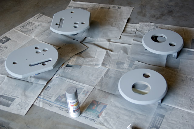 |
The base parts were treated with a Rustoleum sandable primer. Several coats were applied, with sanding between coats. I did this in glancing light to spot any imperfections before the final paint job. |
 |
The final paint job was
Krylon Semi-Flat Black from a spray can. I wish I had good painting
equipment because the finishes done this way appear to be fragile. They
don't resist abrasion well. I'll just have to be careful. Note the long cooling slot on the bottom piece. In the final assembly, it is positioned directly over the amp's heat sinks to provide straight-through air flow for maximum cooling. Two other cooling holes can be seen also. These provide an additional air escape path for cooling the amplifier. |
| Trimming Tweeter Flanges | |
|
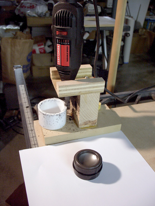
One little visual
distraction was the square flange on the round tweeter. Someone else on
the Orion Users board mentioned that they had trimmed it off with a Dremel tool. I'm not very good at doing anything freehand, so I make jigs where needed. For anyone looking to trim the square flange, this went very well. The picture should reveal much of the design. (click pictures to enlarge) Plastic trims poorly and I had to use a very slow speed to keep melting to a minimum. I didn't try to do it in one pass - I used many small cutting passes to keep the cut clean. The tweeter fit into the pipe end cap, and I rotated the tweeter by hand (carefully!) in the stationary cap. I rotated against the cutting direction to maintain control. The mounting hole in the end cap was slotted so I could adjust the position of the cap relative to the Dremel. Since these pictures were taken, I've also added an adjustment screw that bears against the pipe cap for making very fine adjustments. The jig gets clamped securely to the workbench when trimming. I used a thin (~1/8") piece of Masonite with a 3/4" through hole and a Forstner-made counterbore that left about 1/16" thick material to mount the grinder. I left a little flange on the tweeter so it doesn't get "swallowed" by the PLUTO pipe. This worked out nicely! Note: Steve Roehrig on the Orion/Pluto user group reported success using a similar jig, but he used his drill press instead of a Dremel-type tool. He employed a router bit mounted in the drill press for the flange trimming. This might be superior to my method because of the rigidity offered by a stout router bit + drill press. Also the speed can be slower to prevent melting of the plastic while trimming. |
| Assembly | |
 |
This picture shows a dry fit to see
how the parts would work together. At this time, I double checked Linkwitz' specified dimensions for tweeter positioning relative to the
woofer to ensure that I wouldn't run into trouble after final assembly.
With a mitered tweeter pipe, I didn't have much adjustment. It was perfect. No tweaking needed. |
 |
This shows a test fit of
the base parts after the PVC caps had been fastened using 1/4x20 bolts
and washers. This picture is a little misleading because I had a stub 4"
pipe inserted into the cap. The opening in the top plate for the 4" pipe
is just large enough for the pipe, but is too small for the larger
diameter cap. I had rabbeted a 1/2" deep recess into the underside of
the top plate so that the PVC cap could nest into it. The purpose of this piece was to hide the air vent slot and to hide the PVC end caps. |
 |
I attached the upper
assembly to the 4" pipe using three self-tapping screws through the pipe
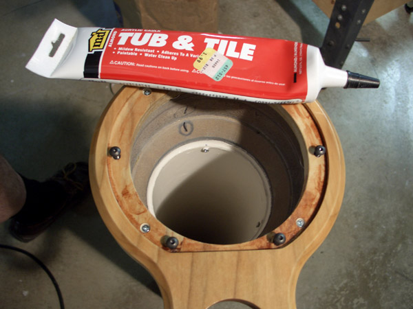
walls into the MDF. Afterwards, I used caulk to seal any gaps between pipe
and the assembly. The three screw-mounting holes were located by cutting a strip of paper and positioning it around the pipe's periphery. Then I unfolded it, measured out three equally spaced marks, and used it to mark the pipe for screw holes. I didn't bother to drill pilot holes in the MDF for the small screws. |
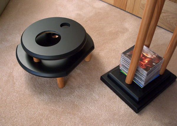 |
Here's the base without the box for the circuitry. If I were to do this over again, I may move the electronics to a separate enclosure. It would offer more opportunities to customize the base of the Plutos. |
 |
If you want Molex-style connectors, buy genuine Molex brand. I purchased some Radio Shack clones, and the pins were absolutely miserable to crimp compared to real Molex pins. |
 |
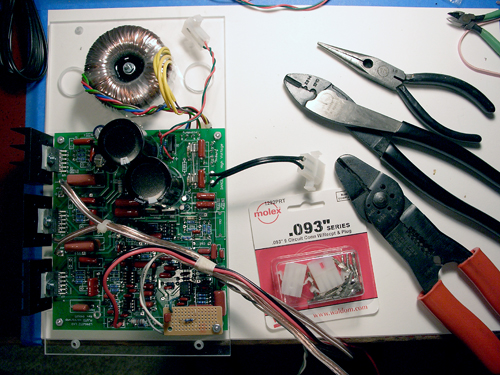
The circuit box and the
circuit board are test fitted to the base. The cutaway part of the
Plexiglas board (seen on the right side) permits straight-path air flow
through the cooling
fins. A straight air path should maximize convection air velocity and
improve heat transfer. All fits well. Good to go. |
| The Finished Plutos | |
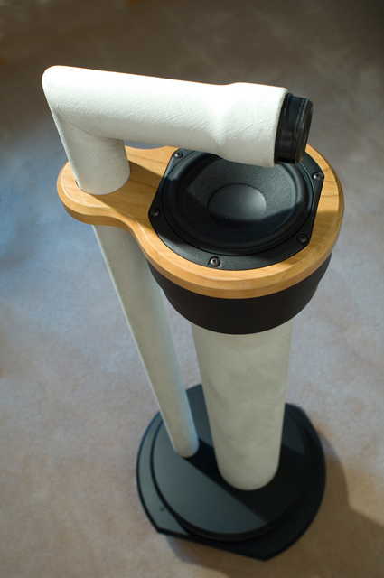 |
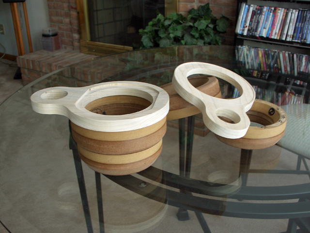
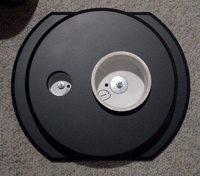
I'm Done! Here's a top view of one finished Pluto. (Click to enlarge any picture) |
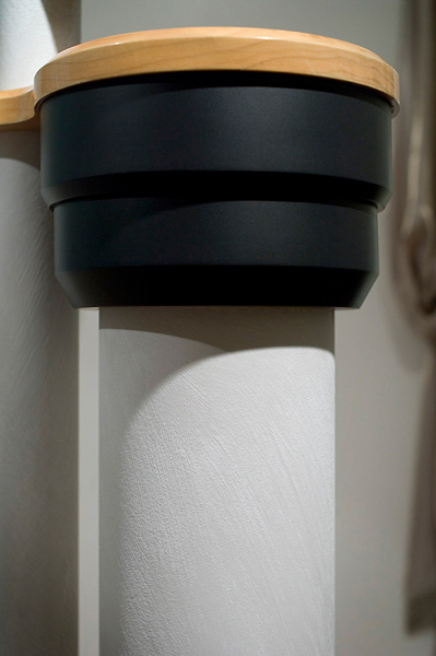 |
This picture shows my MDF version the Fernco rubber coupling. I believe it looks much tidier without the stainless clamps, embossed lettering, etc. It does require substantial fabrication and assembly time though. |
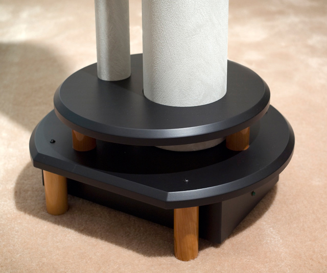 |
Here's the base which includes the electronics. The round top section hides the cooling slots and holes, and hides the pipe cap/pipe junction. |
Since I've built these, the Pluto was revised by Seigfried Linkwitz to use newly designed SEAS drivers to replace the original Peerless mid/bass drivers. The new drivers permit deeper bass extension than this version.
