Build Log: Assembled and working, but not finished.
The sub and this page are still under construction, so there's no picture of it completely finished yet. It is functional though, and I've listened to it. Below are the steps leading up to where I was on 7/24/2011.
This subwoofer design is from John Krutke's Zaph Audio web site. Plans can be found in his archive section.
This subwoofer uses a 12" Dayton Audio RSS315HF-4 (4 ohm) driver and a Dayton 500w plate amp, part #300-806 (now superseded by an updated version) all purchased from Parts Express. The cost of the driver is around $150, and the plate amp is around $325.
Click any picture below to enlarge...
| Cutting Panels to Size | |
 |
Outdoors, I rough-cut a sheet of 3/4"
thick MDF into smaller pieces
using a circular saw and straightedge. The pieces were cut a little
larger than needed.
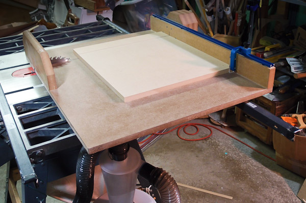
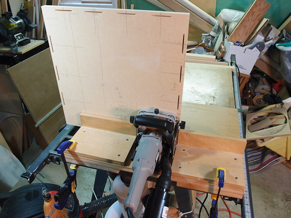
After this rough cutting, I took the pieces to my table saw to cut down to final size. I built a crosscut sled for my table saw that helps keep cuts square, as well as providing a handy stop so that sequential cuts are almost identical in width. Click the picture on the left to enlarge the crosscut sled photo. |
| Joining with Biscuits for Good Alignment | |
 |
While there are many ways to assemble cabinets accurately, I prefer using biscuits. A slot is cut on the mating surfaces of two or more pieces, and a flat, pressed-wood biscuit is inserted into the slot to key the pieces together. Accurate layout is needed, and when cutting slots, I always register on the outside surface of each piece. |
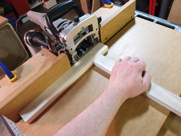 |
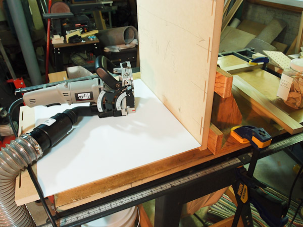
I've constructed a jig for my Porter-Cable biscuit cutter that speeds this work. The pieces being cut rest on a large flat surface instead of the small fence of the biscuit cutter. Here, I'm holding a piece about to be cut with another piece for safety. I don't like to have my hands close to the cutter in case something slips. |
 |
The faces of some panels are cut with
slots, while the edges of other panels have them. This photo shows slots
being cut into the face of panel. I deviated a bit from John Krutke's plans for the cabinet - I wanted to have the sides of the sub continuous (no joints), and to have all the joints come together on the top and bottom panels. I can then double-veneer the top to keep the joints from telegraphing. Since the bottom doesn't really count, having only one surface with all the joints on it means less work when finishing. |
 |
To allow for a compressed gasket, I placed a piece of stout cardboard on a piece of MDF to space the slots for the baffle mounting frame accurately. I couldn't use my biscuit cutting jig here, but it's still a big surface on which to rest the biscuit cutter. |
| Assembling the Amp Box | |
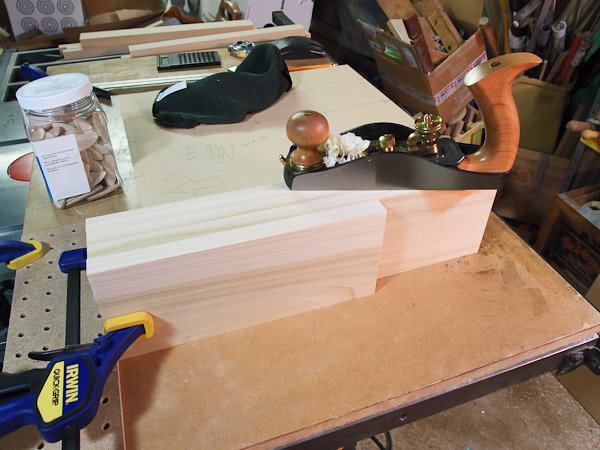 |
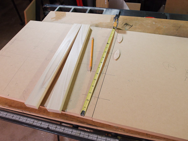
To ensure that the amp box parts are all exactly the same width (desired for good air sealing), I used a smoothing plane on them. Clamped together on a flat surface, the plane shaved them to the same dimension. |
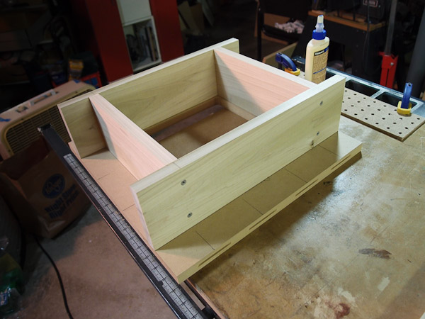 |
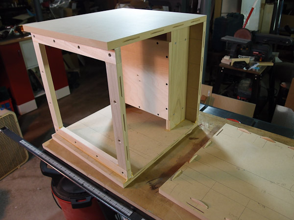
The sealed space for the amplifier was created by the poplar boards glued and screwed into an H frame. |
 |
When the H-frame was dry, it was glued
to the back panel. I used no biscuits here because I couldn't easily
figure out how to register them. Besides, the long ends of the H frames
would also be glued to the top and bottom anyway, and that's
sufficiently strong. In this picture, I had already used a Bosch jigsaw to cut out the opening for the amplifier on the back panel. |
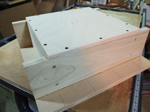 |
Once the H-frame was attached, I cut a piece of 1/2" baltic birch plywood to cover over the space. |
| Marking Amp Box Mounting Holes | |
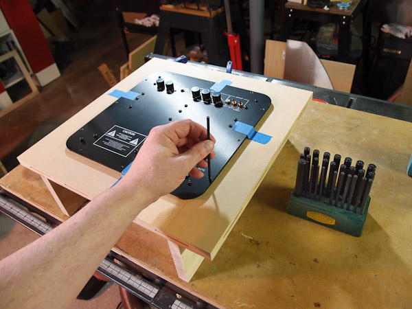 |
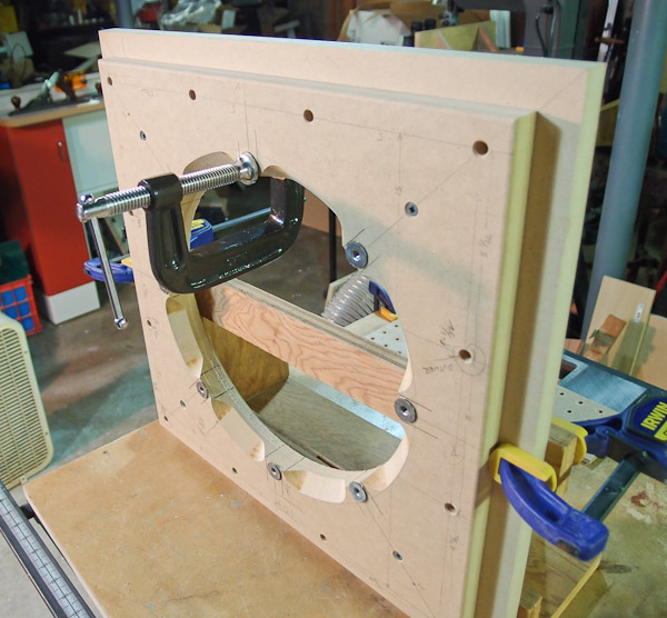
With the plate amplifier centered and taped temporarily in position, I used transfer punches to mark the locations of the mounting screws. Once marked, the amp was removed. |
| Assembling the Baffle Mounting Frame | |
 |
A rectangular frame of poplar wood recessed into the box provides a mount for the baffle. Small "face frame" (FF) biscuits were used to join the frame. Larger #10 biscuits hold the frame to the inside of the cabinet. That puts them in shear for the baffle mounting load, which is ideal. |
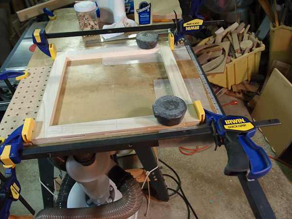 |
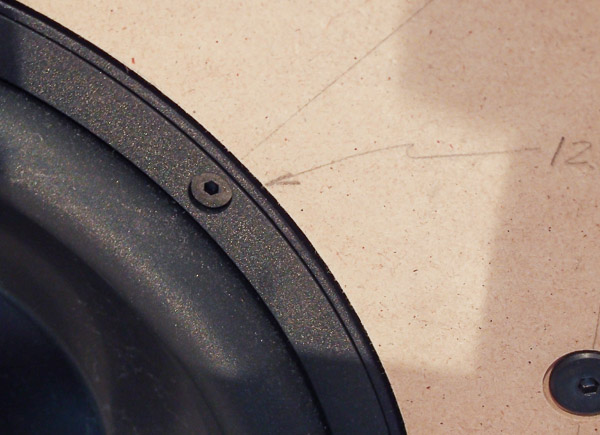
The baffle mounting frame was glued together as a sub-assembly. Five-pound lead weights helped maintain a level face for the glue-up. I was very careful to maintain squareness during glue-up. I checked it with a 12" Starrett combination square just after clamping, and made small adjustments until perfect. |
| Brace Fabrication | |
 |
John's design uses a unique set of internal braces made from 2x2 lumber. His design information gives an explanation, and he claims that it is ideally suited for a symmetrical box like this one. It IS easy to fabricate these braces! |
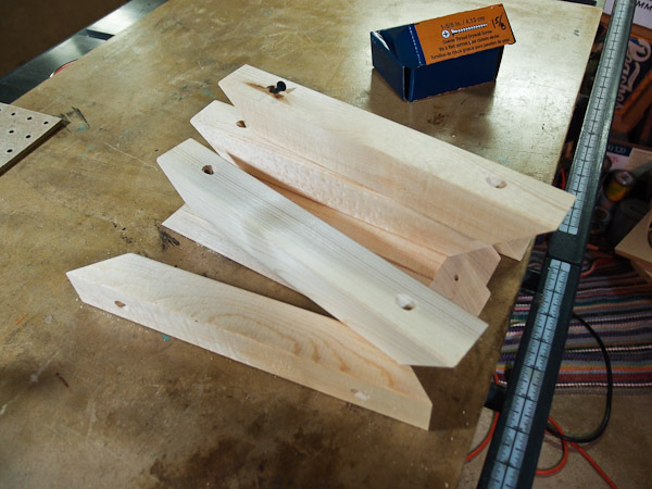 |
After cutting the 45* miters on each end of the braces, I used a drill press to cut counterbores for the screw heads and then drill the through-hole. I used a Forstner bit for the counterbores, and then used the "dimple" left in the center as a guide for the through-hole. I used a drill press fence and fence stop to aid this work. If limited to a simple hand drill, I'd just drill the through-holes and forget the counterbore. |
| Inserting Baffle Mount T-Nuts | |
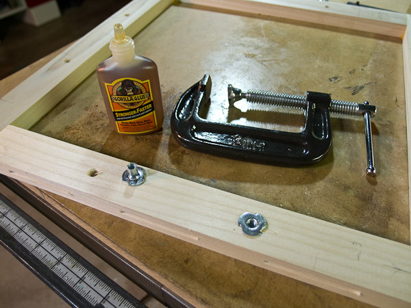 |
I purchased 1/4-20 T-Nuts from a local hardware store for the baffle mount. The T-nuts have prongs that penetrate into the wood to keep them from spinning when bolts are tightened. I press them in using a c-clamp, and use a little Gorilla glue to ensure that they don't pop out. |
| Baffle Fabrication | |
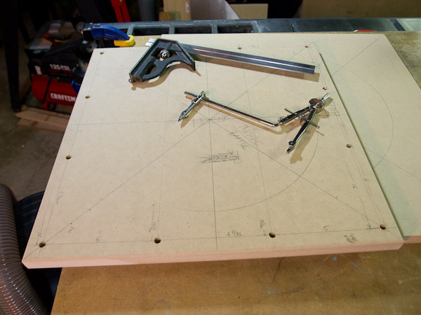 |
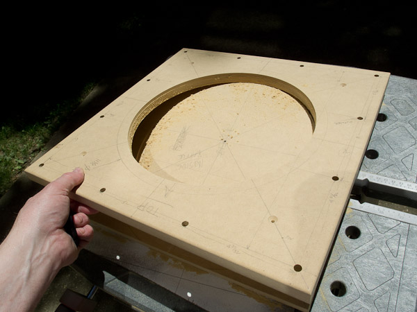
Every cut is drawn onto the surface
before routing. It reduces the chance for mistakes. I use my old
drafting compass with an extension beam for this work. After layout, I drill a 1/8" hole at the center of each circle for the circle jig pin. Usually I do this on the drill press to ensure a hole square to the surface, but this baffle was too big for my drill press to "reach" into the center. I use a hand drill instead with a simple block of wood to aid drilling the hole straight. See a photo of the wood block on a drill further down the page. The block of wood has been drilled square on the drill press, and it works fairly well as a guide. |
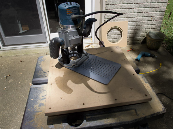 |
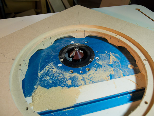
Routing MDF is messy. I try
to do as much routing outdoors as possible. I can use a leaf blower to
clean up afterwards. Shown is the large Jasper Circle Jig on a Bosch plunge router. A 1/8" pin serves as the center of rotation for the router with jig attached. One baffle front is shown in the background of this picture with the driver recess and through-hole already cut. The inner baffle is shown about to be routed. I use a 1/4" spiral upcut bit to cut the through holes. The bits are Bosch brand, purchased from Lowe's. I had trouble with Freud bits in the past. Each cut is about 1/8" deep, and they progress until the hole is through. The turret-style depth stop on the Bosch router is ideal for incrementing these cuts ever deeper. |
 |
For this job, I used double-stick tape to hold the pieces to a backing board for cutting. The tape's purpose is to prevent the center piece from coming adrift when I cut through the MDF, which may cause an unplanned divot cut into the part. The backing board, of course, prevents the router from cutting into the work table. |
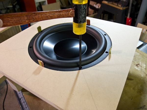 |
To mount the driver, I'll use hurricane nuts on the back side of the baffle. To mark the holes for their location, I shimmed the driver to the center of the recess using pieces of cardboard, then lightly punched dimples into the MDF using a transfer punch. The punch centers on the driver's screw hole for an accurate layout. The driver must not move between punches in different holes, and the shims combined with a 25lb driver were sufficient. |
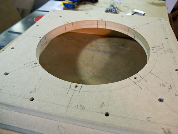 |
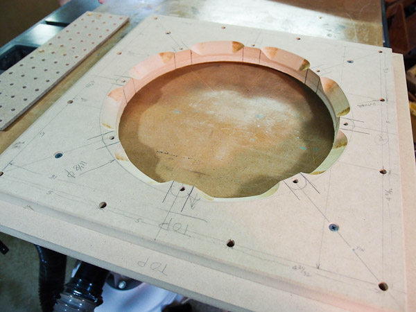
To provide sufficient airflow around the back of the driver, it's customary to cut relief chamfers into the back of the baffle. Full thickness is needed in the lands where the hurricane nuts will be pressed in, but the in-between areas need to be chamfered away. In pencil, I marked the future location of the hurricane nuts so that I knew where to stop cutting. |
 |
A router table with a 45 degree chamfer bit cut the chamfers. A handheld router could be used, but a router table allows a little more control. I had built this router table last summer, and I was determined to put it to use. |
 |
A picture showing the chamfered areas between the hurricane nut "lands" during cutting. Note the ultra-fine sawdust from the MDF. I had a shop-vac attached to the router table, but it's not 100% effective. It helps, though. |
 |
The chamfers are complete. Especially needed in thick baffles, chamfering aids the airflow behind the driver. |
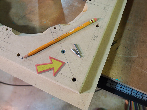 |
This detail shows how I had
pin-registered the inner baffle to the outer baffle. This was done prior
to routing the holes so that I could work with the pieces separately.
Then, when routing was done, the two baffles lined up perfectly again
when assembled together.
I put two pins in the baffle on opposite ends of one of the diagonals. Pins locate better than screws, which serve merely to clamp the two pieces together. Note that the pins were already in place when I routed the chamfers in the driver cutout, but I didn't show this detail in an earlier step. I purchased the 1/8" steel pins in a box of 100 from McMaster-Carr online. They also serve double-duty as spare pins for my Jasper circle guide. |
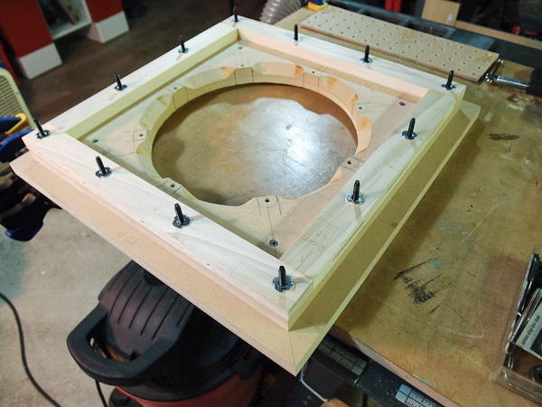 |
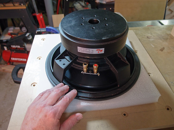
I checked the alignment of mounting holes for three mating items - the baffle mounting frame (shown on top here), the inner baffle which nestles inside the cabinet, and the outer baffle. All screws went in fine without serious binding that might be caused by hole location mismatch. I was a little concerned about matching up three pieces well enough, but it turned out OK. |
 |
Time to press in the hurricane nuts that
hold the driver to the baffle. Again, I used a c-clamp to squeeze them
into their appropriate holes, and I added a couple drops of Gorilla glue
to make sure they don't spin in place when screws are inserted. Note the use of an old plywood 90 degree jig to hold the baffle upright for this operation. It seems that I never throw anything away, and some unused things come in handy even after years of gathering dust. |
| Gluing the Cabinet Together | |
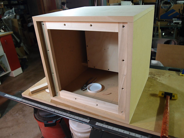 |
Dry Fit: The first task before gluing everything together is to do a test fit without glue - a "dry fit". The biscuits make this a "snap-together" test. They hold things in position well enough so that I don't have to juggle a pile of loose parts. |
 |
Here's a chance to assess the fit of mating parts before gluing. A tight-fitting joint is desired, and all joints in this project looked fine like the picture shows. After the check, everything is taken apart again for gluing in steps. I usually glue up subassemblies in larger projects like this one. |
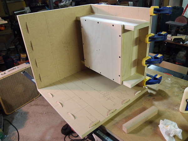 |
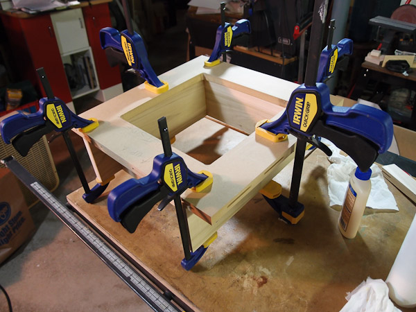
In this photo, the rear panel and the bottom panel are being glued together. I used the right side panel, with biscuits in it, to align the bottom and rear panels correctly. A piece of waxed paper placed at the joint prevented the bottom/rear subassembly from gluing itself to the right side at this time. Not shown in the photo is that I also snapped on the other side panel (would be located on the top at this orientation) to also locate the glued panels for assembly. |
 |
After the two panels shown above had dried, I then glued and clamped the baffle mount frame to the bottom panel. The other panels pictured are there merely to have their biscuits align the assembly in the proper location for drying. Slips of wax paper keep squeezed-out glue from sticking to the panels used to register the assembly. After the glue dries on the other panels, they were removed, and glued together later in separate steps. |
 |
When the baffle mount frame glue had dried from the previous step, the top panel was then glued to the subassembly. I am getting ready to glue in this step, and the panel partially shown on the left of the photo would be used to register the glued pieces to keep things square. The panels themselves become part of an assembly jig. |
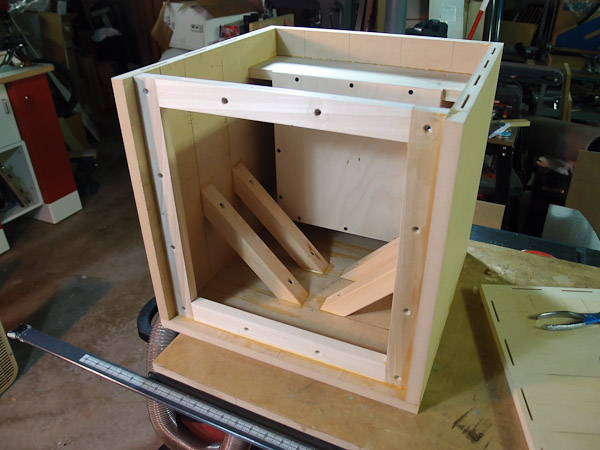 |
Because one side was still detached, I had ample room to start adding some of the internal 2x2 bracing with screws and glue. It was easier at this point because there was room to work, but I could have waited until the end. There are still more braces to attach, but that can't be done until after final panel is glued on. |
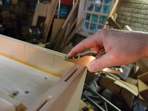 |
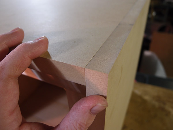
Regardless of the care taken beforehand, there are always slight mismatches between adjacent surfaces after gluing. I used a small block plane here to quickly level a small mismatch between two adjoining panels. It's faster than sandpaper, and likely more accurate because of the dead-flat bottom on the plane. |
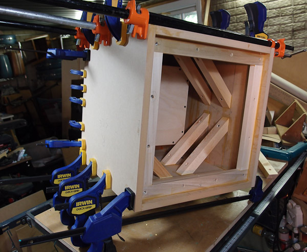 |
The final panel is glued on. Not all clamps are shown in position yet. I still had to attach several small 6" clamps to the interior baffle mounting frame to secure it against the inside of the panel shown at the picture's left. |
| Final Assembly Details | |
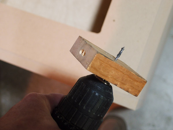 |
Attaching the plate amplifier to the
back: drilling pilot holes square into stock without a drill
press is challenging. To provide a "portable guide", I pre-drill a clearance
hole in a small block of wood with my drill press. To use it, I put it
on the hand drill with bit, position the point of the drill in a
punched "dimple", slide down the wood block until it's flat against the
surface to be drilled, and that guides the drill in straight. I prefer to use German-made Colt drills (when possible) with wood or MDF. The brad point of the drill reduces bit wander when drilling deep holes, and they are very well made. Unfortunately, they have only 1/32" increments between sizes. I'd prefer to have 1/64" increments. They still got the job done nicely for these pilot holes though. |
 |
Installing gasket material onto the driver. I used Parts Express #260-542 speaker gasket tape. It comes in a 1/8" thick x 1/2" x 50 ft. roll. Tip for first-time users: it won't bend around curves until you remove the paper backing. |
 |
I used #10-32 flat head socket screws (1-1/2" long) to mount the driver to the baffle. The driver mounting ring counterbore for the screw head measured 0.390", and the #10 FH screws have a 0.385 diameter head. That provided a nice, tight fit. [I don't remember if I had to enlarge the hole in the driver rim to clear the #10-32 threads.] |
| First Sound | |
|
|
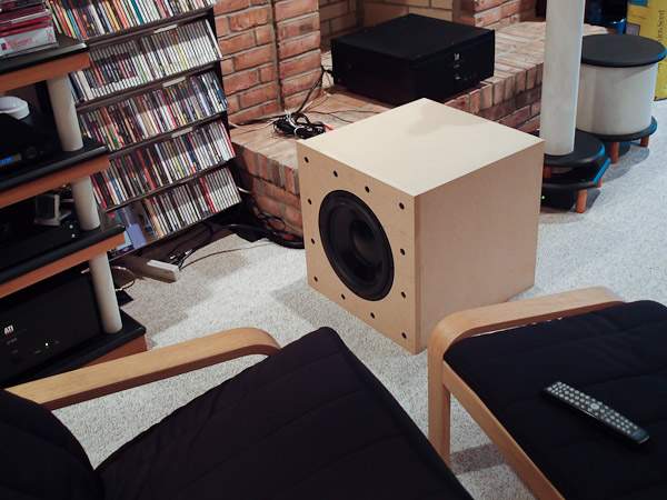
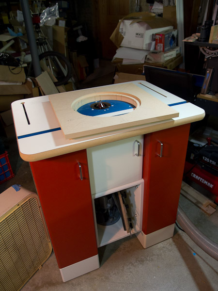
First impressions: It is a BIG box. It
weighs about 70 lbs, and I
wrenched my back moving it into position. The sound is impressive though. It digs deep enough to make my pant
legs flap in the breeze when playing bass-heavy material like
Herby Hancock's Dis is Da Drum or Virgil Fox's The Bach Gamut
organ music. There's some rolling, deep bass in Beats Antique's
Tribal Derivations (track #6 - Derivation) that becomes very
audible with this employed. It's not just audible, it's tactile enough
to feel. In some cases, it makes your head feel funny. I haven't trimmed the baffle edge flush with the sides of the cabinet yet, so it's very ugly right now. I won't trim it until I know whether I will paint or veneer the cabinet. Veneering adds thickness to the box, so a flush trim of the baffle at this point would not be flush after veneering. Paint is cheaper, but requires a lot of prep time. Decisions... |
 |
My big problem now is where to put it in
my room. It commands attention out in the open. One option I'm
considering is to make it into an end table, with the driver firing
downward. I'd likely have to move the amp to an external location on the
equipment rack and probably build separate box for it. If I chose this
route, I'd fabricate a table top from solid wood
and attach it to the subs' current back side. The back would then become the top. I've seen very nice, furniture-quality examples of
this approach on the internet, but it would be a lot of work to do. Finishing always takes longer than building! |
It really does add another dimension to the music on some speakers. It should nicely flesh out the sound of my Zaph ZDT3.5 speakers (not shown here). Those speakers could use a little boost in the lowest registers, and this sub delivers it in spades.
Things I'd do differently: The amp mounting plate is about 1/4" proud of the back surface, and it sticks out as an unfinished detail. If I were to do this again, I'd rebate the back side of the sub to flush mount it. I can't do it now because there isn't enough depth in the internal amp box. However I can still flush mount the amp by fabricating a frame from 1/4" Masonite and attaching it to the back of the sub before finishing. I have to consider if it's worth doing.
Bill Schneider
7/24/2011