Meeting 5
The proper proof - a contact sheet exposed just enough to let the clear film produce almost maximum black using normal contrast (#2). Methods for determining the print exposure time to do this. If employed regularly, the proper proof will allow you to monitor the chain of processes beginning with camera exposure through film processing.
Perfecting the print - Methods for getting better prints employed by most printmakers - choosing the right contrast to use, and dodging and burning.
Enlargers
A good web site overview of enlargers can be found at
http://www.darkroomsource.net/enlargers.shtml
Condenser heads
Enlargers can have different types of lamps in the lamphouse. Most common is
a tungsten bulb mounted above a pair of condenser lenses. The condenser
lenses must be configured properly to provide even illumination across the
entire negative. In our Omega D5 enlargers, the condenser lenses are
repositioned to suit the focal length of the enlarging lens. We have three
different enlarging lens focal lengths available for use with various film
sizes:
|
|
|
|
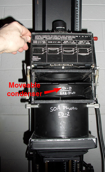
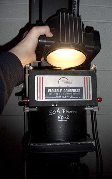
| The variable condenser is accessed through the flip-up front panel in an Omega D5 enlarger. Merely reposition the condenser as indicated to provide even light illumination for various enlarging lens focal lengths. | The light source in this condenser enlarger is a household sized enlarging bulb. They differ from standard household bulbs because there is a very even white coating on the globe, and no trademarks or other printing are stamped onto the bulb. |
| Film Size | Minimum Enlarging Lens f.l. | D5 Condenser Position |
| for 35mm negatives | 50mm enlarging lens | 3 (bottom) |
| for 120 negatives (2-1/4 inch wide film) | 75mm or 80mm enlarging lens | 3 (bottom) |
| for 4x5 inch negatives | 135mm enlarging lens | 1 (top) |
Sometimes better results can be had using a longer enlarging lens for a given negative, particularly if you experience significant vignetting of the corners. (For example, using a 135mm enlarging lens for 120 film instead of the suggested 80mm.) Also, a slightly longer lens allows you to make smaller enlargements. This might be useful if the enlarger is lowered against the bottom stop and the photo is still too big for your needs (i.e. 2"x2" passport photos).
Some enlargers (i.e. an older Omega DII) require that you to change entire condenser lens sets to accommodate various enlarging lenses. Having a separate set of condenser lenses for each enlarging lens is both expensive and slow to use.
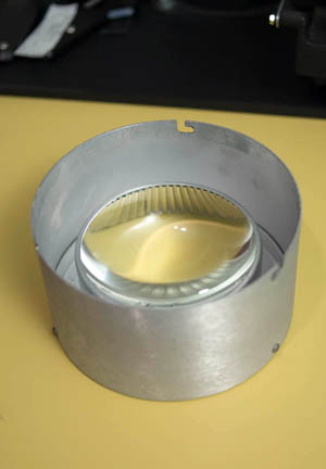 |
Shown here is a set of condenser lenses for an older
Omega DII enlarger. This set is sized for 75-90 mm enlarging lenses
typically used for 2-1/4 inch medium format film. Other sizes were also
manufactured, with the large 6" diameter lenses meant for 135-162mm
lenses. In this system, each time an enlarging lens was changed, the condenser set had to also be changed. It was time consuming. If an incorrect set of condenser lenses was installed, severe light falloff at the corners of the projected negative was the usual symptom. Later enlarger designs used variable condenser lens sets. |
Color heads
Color heads generally use a high-intensity tungsten lamp, and employ a
light mixing chamber with a diffuser to provide diffuse illumination through the
negative. The diffuse illumination prints traditional black and white films with
lower contrast than a condenser head due to an effect called the Callier Effect.
The contrast using diffuse illumination matches the contrast of a normally made contact sheet.
As a plus, diffusion head also visibly reduce dust and scratches in the print.
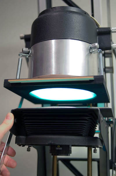
Cold light heads
Not as common, but still found in many b/w printing establishments, is a
cold light head. A cold light is a fluorescent lamp bent into a grid shape
above a translucent plastic diffuser situated just above the negative.
Aristo is a company that manufactures
cold light heads for various enlargers.
Originally cold lights were made for fixed contrast grade printing papers and were very blue. With variable contrast (VC) papers the blue light produced very high contrast and was difficult to filter. Newer versions using the V54 lamp were designed to be used with VC papers. They respond well to Kodak and Ilford contrast filtration.
Cold lights, although not entirely cold when operated, run much cooler than tungsten bulbs and reduce negative popping due to thermal effects. The contrast in enlargements made with diffuse light sources matches the contrast found in the contact sheet. Diffuse lights do not increase print contrast like condenser lampheads do.
 |
 |
|
| A very old Omega DII (precursor to the D2) 4x5 enlarger equipped with a Zone VI cold light head. The tungsten lamphouse has been removed because the cold light fits where the condenser lenses once were. | This enlarger is outfitted with a homemade filter drawer (See Photo Techniques Magazine March/April 2003) to permit filtration of the light above the diffuser. Because of the Plexiglas diffuser disk is situated immediately underneath the filters, scratches and other imperfections in the filter do not matter. | |
 |
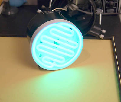 |
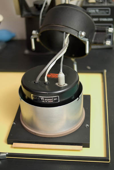
|
| A cold light usually has two leads - one for a heater, and one to light the lamp. This Zone VI head has an additional lead/socket for the light-measuring photocell. | My Zone VI cold light removed from the enlarger. The fluorescent grid is visible here because the Plexiglas diffusion disk has been removed. The lamp is an Aristo V54 that produces a spectrum designed for variable contrast papers. I would guess that Aristo made this head for Zone VI studios when they were in business. Some Zone VI products are now sold by Calumet. Zone VI cold light heads had a built-in photocell that measured light and permitted an external feedback/stabilizer circuit to maintain constant illumination. | |
 |
||
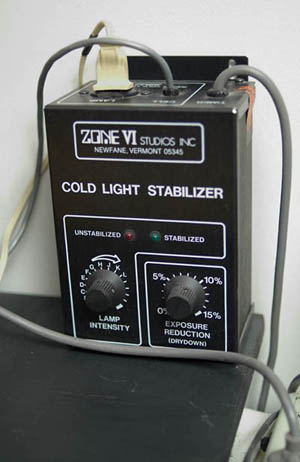
| This device is a cold light stabilizer that maintains a
constant level of illumination. It employs a photocell mounted in the
cold light head to monitor the brightness level. The electronics
compensate for the natural tendency for cold lights to become brighter
as they heat up during the exposure. This device also permits luminance
adjustments (dimming) within a few stops range, and has a print dry-down exposure
reduction circuit that I don't use. This Zone VI unit is no longer made, but a company called Metrolux makes a similar unit. Calumet Photographic sells several versions of the Metrolux unit... here's one.. (Sadly, Calumet in Chicago is out of business now) |
Alignment
Enlargers should have the negative, lens, and easel all parallel to each other.
If they are not parallel, the enlarger is said to be out of alignment and will
produce prints having a sharp picture on one edge (or middle), but are unsharp
on the other.
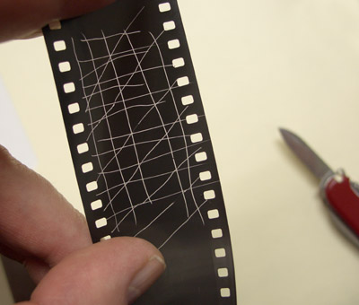
A quick test of alignment can be done by eye using a piece of exposed and developed film in which the emulsion is scratched with a pin or the point of a knife. Place this in the enlarger just like any other negative, turn the lamp on and focus the scratches onto the easel with the lens fairly wide open. This provides a very high-contrast target that is easy to evaluate visually. If one side of the projected negative is unsharp, enlarger alignment is usually the culprit.
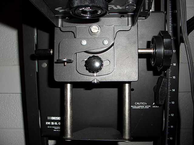
This Beseler 23C enlarger above has a left-right adjustment for lens-stage alignment. The knob in just under the enlarging lens can be loosened, and the lens stage can be adjusted to provide the sharpest image from left to right.
The Omega D series enlargers have an adjustable negative stage. There are four screws and nuts that attach the lens stage plate to the mounting brackets. This adjustment is a delicate affair on an Omega D because it's easy to end up with a warped plate that is not flat, or is positioned very low on the brackets. In addition, it's possible to have the lamp house not seat flat against the negative holder causing light to leak into the room.
It's also quite possible with D series enlargers that the heavy enlarger assembly (rails and all) has caused the baseboard to warp where the enlarger attaches. If sufficiently warped, you will not have enough adjustment to achieve alignment. I have reinforced my Omega D2 baseboard with angle iron on the bottom, and a steel backing plate under the baseboard where the bolts hold the enlarger to the baseboard to prevent any warping.
There are a number of alignment adjustment tools available in addition to the scratched film mentioned above. Bubbles levels provide an inexpensive method. If you use a bubble level, it's best to start by leveling the baseboard of the enlarger, and then work up to the lens stage and to the negative stage. Expensive and precise optical methods like the Zig Align that use multiple reflections (essentially a pair of mirrors facing each other) are also available. I've been satisfied with my bubble level adjustments, and have sharp film grain from corner to corner in my prints.
Testing film
There are two factors that go into a good negative. First, is the ISO chosen for
the film a reasonable choice? Second, has the film been developed properly?
Some photographers use expensive densitometers to test film. These devices are useful, but a careful b/w photographer can get very close using a simple procedure available to any darkroom worker. The test steps can be found here:
Film ISO setting is evaluated by looking at the negative itself. The frame exposed at 5 stops under the metered exposure should just barely be visible against the film edge. It should look just slightly grayer than the clear, unexposed film around it. If the gray patch is not there, you need to reduce the ISO setting and try again before you can evaluate the developing time. If the film patch is too dark (approaching medium gray), you might try increasing your camera's ISO when shooting this film to reduce film exposure.
After you have established the ISO setting that is correct for your camera/meter, then you may legitimately proceed to judge developing time. If the ISO part of this test isn't done yet, don't waste your time making a contact sheet.
If your ISO test is OK, a developing time evaluation can be made by making a proper proof (exposed so that the sprocket holes almost go max paper black) while covering up half of the overexposed frame with a sheet of opaque material. The covered area should be pure white because it gets no exposure. The overexposed frame in the contact sheet should be just ever-so-slightly darker than the adjacent white area. (It may not show clearly in this web photo.)
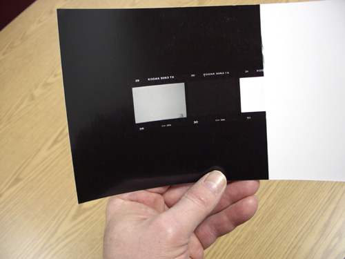
While the extra frames shown on the left of the overexposed frame don't need to be printed, they are shown in this picture.
![]()